G12 Troubleshooting Guide

The G12 power distribution panel receives the signals sent from the Touchscreen/Switch Panels/App and performs the actions that have been requested by activating and deactivating the required 12VDC circuits.
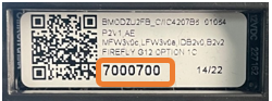
Note - The G12 comes in several hardware configurations, known as Options. The ID Sticker will identify exactly which Option was installed in the coach (Example - Option 1).
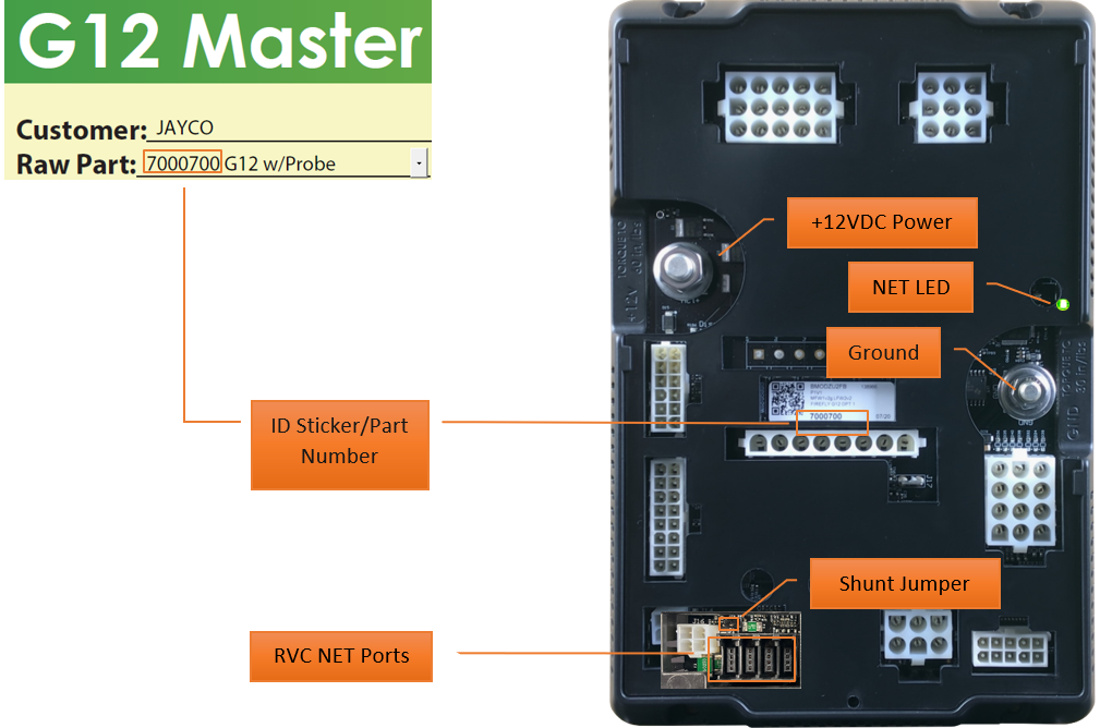
Shunt Jumper
When both pins are closed (terminated), 120-ohms of network resistance is added to the system. When the pins are open, no resistance is added to the system. Note - this feature will not appear on all G12 models.
RVC Net Ports
These ports provide direct access to the RVC Network for wired RVC devices such as wired switch panels, touchscreens, Vegatouch modules, etc.

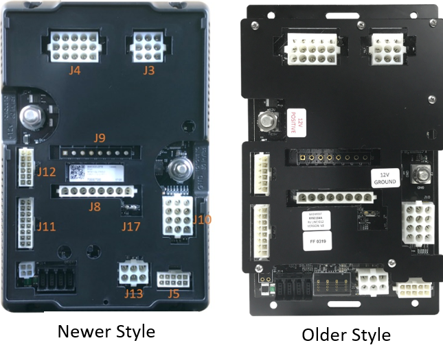
G12 Styles
 There are two slightly different looking G12 styles available. Newer
versions will have the connector names molded into the plastic cover
as shown.
There are two slightly different looking G12 styles available. Newer
versions will have the connector names molded into the plastic cover
as shown.
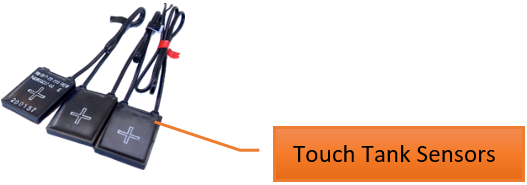
G12 Tank Options
7000700 (Option 1 and 1C)
- Uses Probe tank sensors

7000701 (Option 2)
- Uses TruTank sensors

7000702 (Option 3)
- Does not support holding tanks
7000703 (Option 4)
- Uses Probe tank sensors
7000704 (Option 5)
- Uses Probe tank sensors
7000705 (Option 6)
- Uses TruTank sensors
7000708 (Option 2A)
- Uses Touch tank sensors
Troubleshooting
 Before troubleshooting, verify that the correct G12 part number has
been installed in the coach.
Before troubleshooting, verify that the correct G12 part number has
been installed in the coach.
Table of Contents
1 - Verify that the NET LEDs are solid green (not flashing).
Use the LED Key to determine the network status for most system components. If an LED is displaying anything other than solid green, refer to the Network Troubleshooting Guide to verify the network configuration.
Fast flashing Green light (4 times/sec) - Device is attempting to make initial connection.
Slow flashing Green light (1 time/sec) - Device was online but has been offline for at least 5 sec.
Solid Green - Device is connected to network and it communicating properly.
Solid Red - Device has gone offline and is not connected to a network.
Alternating Red & Orange - Device has gone offline and is trying to re-connect (within 30 sec).
Alternating Green & Orange - Device is currently online but has gone offline 2 or more times.
2 - Does the Logic Controller (LC) match the GUI version?
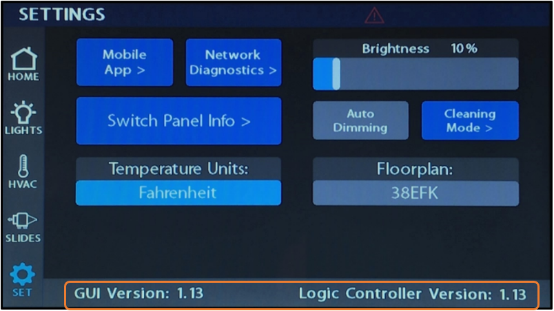 Tap on the settings button from your primary multiplex screen to
locate the GUI and LC versions. In most cases, you'll want the
versions to match. In some systems, the versions are required to
match or the system will produce a version mismatch warning message
upon bootup and will not operate until the mismatched versions have
been updated to match. If the LC version is displaying dashes
instead of numbers, this indicates that there is no programming on
the module and programming needs to be loaded.
Tap on the settings button from your primary multiplex screen to
locate the GUI and LC versions. In most cases, you'll want the
versions to match. In some systems, the versions are required to
match or the system will produce a version mismatch warning message
upon bootup and will not operate until the mismatched versions have
been updated to match. If the LC version is displaying dashes
instead of numbers, this indicates that there is no programming on
the module and programming needs to be loaded.
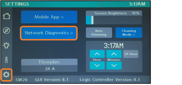
3 - Check the G12 Firmware version.
Identify the Firmware Version on the G12. To do this, navigate to the Settings page and tap the Network Diagnostics button.
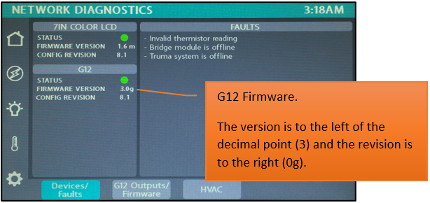
Once you are on the Network Diagnostic page, you will see a section labeled G12. Under the G12 there is line labeled Firmware Version.
Note - Firmware versions will increment by one letter with each update.
Minimum Required Firmware Versions
V1 Firmware
With TruTank - 1v2p
W/O TruTank - 1v2g
V2 Firmware
With TruTank - 2v10
W/O TruTank - 2v1m
V3 Firmware
With TruTank - 3v0f
W/O TruTank - 3v0f
If your G12 is not at the correct version, please contact Firefly.
4 - Is the G12 receiving adequate voltage?
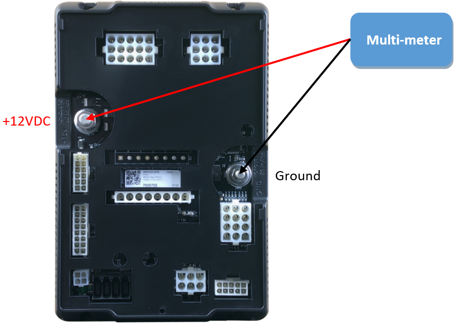
Use a multi-meter to measure the incoming voltage to the G12 panel. If the G12 receives less than 9VCD, it will turn off. Voltage should read between 9-14VDC and should never exceed 18VDC. If a unit has more than one G12 you'll need to check the power coming to each G12 panel.
5 - Check Outputs.
Disconnect the wire out of the suspected plug to test the output. Note - make sure to turn the output circuit ON before testing. The house power reading should match the output that you're testing. If the pin does not output any voltage, you'll need to replace the G12 panel. If you have adequate voltage at the G12 output, then check the wiring to the device in question. The G12 is working as it should.
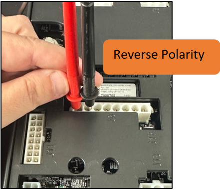 Reverse polarity outputs will operate in pairs. For this process,
think about how a slide operates. One channel will extend the slide, and
the other will retract the slide. If channel 1 is receiving +12VDC to
extend the slide, channel 2 will be Ground (-12VDC). When it's time to
retract the slide, channel 1 will be Ground and Channel 2 will receive
+12VDC. In essence, the output of both channels has been flipped to
reverse the process. When measuring reverse polarity output voltage,
touch the probes of your multimeter to the correct pair of output pins,
then extend and retract the Slide. You'll notice that both +12VDC and
Ground will switch between channels depending on whether extend or
retract has been pressed.
Reverse polarity outputs will operate in pairs. For this process,
think about how a slide operates. One channel will extend the slide, and
the other will retract the slide. If channel 1 is receiving +12VDC to
extend the slide, channel 2 will be Ground (-12VDC). When it's time to
retract the slide, channel 1 will be Ground and Channel 2 will receive
+12VDC. In essence, the output of both channels has been flipped to
reverse the process. When measuring reverse polarity output voltage,
touch the probes of your multimeter to the correct pair of output pins,
then extend and retract the Slide. You'll notice that both +12VDC and
Ground will switch between channels depending on whether extend or
retract has been pressed.
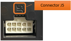
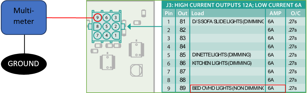
Once a light or function has been toggled ON (from the Screen, Touch Panel or App), the pin output for that particular circuit will activate and the G12 will send 12VDC to the designated device. In this example, the Bed Overhead Lights have been toggled ON, so the G12 panel is sending +12VDC to pin 9 (Connector J3, Output 89).
Verify Positive output voltage by testing the pin with a Multimeter as illustrated below. Test Negative output voltage (on circuits that produce -12VDC) by applying Positive and Ground where necessary.
- Check the wiring to the lights.
If no output voltage is measured:
- Check the Net Diagnostics Screen (Outputs tab) to ensure that the Green LED shows status.
- If no status is showing, contact Firefly.
- If the status light operates correctly, verify that your Multimeter is functioning properly.
- Replace the G12 if necessary.
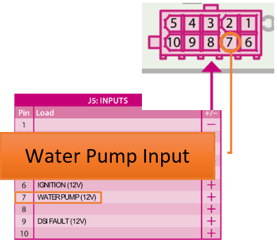
6 - Check the Inputs.
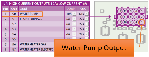
Some outputs will only work when an associated input signal is required (example - water pump may require an input signal coming from a rocker switch).
Check the Net Diagnostics status light:
- If the input is off, the light should be off.
- If the light is on, disconnect the input connector from the G12.
- If the light goes off, check the wiring.
- If the light stays on, replace the G12.
If an input is active and the light is not coming on, disconnect the connector and test the wire to make sure that the input voltage on the wire measure between 9-14 volts.
Does the voltage measure correctly?
- If yes, use a jumper wire from the correct polarity on the Power or Ground stud on the G12 and jump to the input. If it does not come on, replace the G12. If it does come on, check the wire.
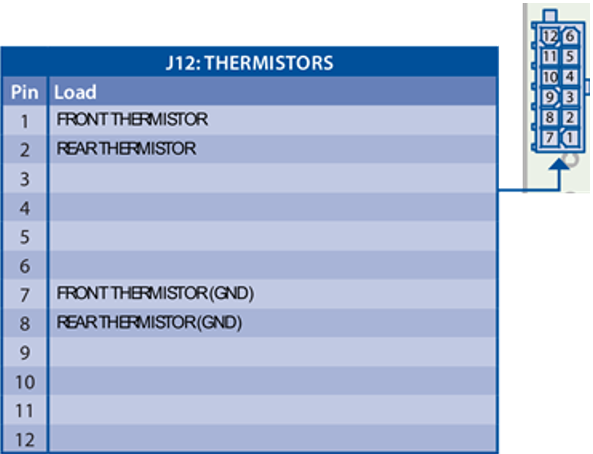
Temperature Inputs
Temperatures (by zone) are reported to the G12 by thermistors located throughout the coach.
If a temperature is displaying dashes on the screen instead of a valid temperature reading:
- Verify that the thermistor has been plugged into the correct pins on connector J12.
- Plug a known working thermistor into the pins in question to verify if it works.
- If it works, replace the failed thermistor.
- If it does not work, replace the G12.
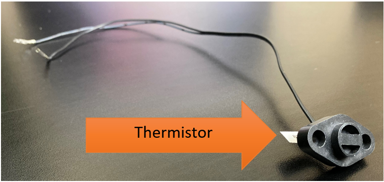
Note - If the thermistor in question does not resemble this image, Firefly did not supply it. Contact the coach manufacturer for additional information.
Holding Tanks (Probes)
If a system uses Probes to report tank capacities, the values will display in thirds on the touchscreen.
If a Tank value is reporting an invalid reading:
- Test with a known working probe by connecting it directly to the G12.
- If it works:
- Check the sensor.
- Check the wiring harness.
- Check the ground for the sensor harness.
- If it does not work:
- Replace the controller.

LP Tank
If a tank is overfilled (above 79%), the percentage will change to “Disc” and the graphic will show empty. This message could also be caused by a disconnected LP input.
A filled value of between 74% - 79% will show “Full” for the percentage and the graphic will show full.
A filled value of between 25% - 74% will display the accurate percentage and graphic level.
A filled value up to 25% will result in the percentage displaying “Low” and the graphic showing the accurate level.
If the tank is not overfilled and but value is displaying “Disc”:
- The LP is most likely disconnected. Use a known working LP sensor to test.
- If the LP value does not change, replace the G12.